MySQL Workbench Release Notes
The vertical toolbar on the left side of an EER Diagram has six foreign key tools:
one-to-one non-identifying relationshipone-to-many non-identifying relationshipone-to-one identifying relationshipone-to-many identifying relationshipmany-to-many identifying relationshipPlace a Relationship Using Existing Columns
Differences include:
-
An identifying relationship: identified by a solid line between tables
An identifying relationship is one where the child table cannot be uniquely identified without its parent. Typically this occurs where an intermediary table is created to resolve a many-to-many relationship. In such cases, the primary key is usually a composite key made up of the primary keys from the two original tables.
A non-identifying relationship: identified by a broken (dashed) line between tables
Create or drag and drop the tables that you wish to connect.
Ensure that there is a primary key in the table that will be on
the “one” side of the relationship. Click on the
appropriate tool for the type of relationship you wish to create.
If you are creating a one-to-many relationship, first click the
table that is on the “many” side of the relationship,
then on the table containing the referenced key. This creates a
column in the table on the many side of the relationship. The
default name of this column is
table_name_key_name where the table
name and the key name both refer to the table containing the
referenced key.
When the many-to-many tool is active, double-clicking a table creates an associative table with a many-to-many relationship. For this tool to function there must be a primary key defined in the initial table.
Use the menu, menu item to set a project-specific default name for the foreign key column (see Section 9.1.1.1.5.4, “The Relationship Notation Submenu”). To change the global default, see Section 3.2.4, “Modeling Preferences”.
To edit the properties of a foreign key, double-click anywhere on the connection line that joins the two tables. This opens the relationship editor.
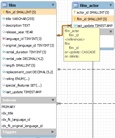
Pausing your mouse pointer over a relationship connector
highlights the connector and the related keys as shown in the
following figure. The film and the
film_actor tables are related on the
film_id field and these fields are highlighted
in both tables. Since the film_id field is part
of the primary key in the film_actor table, a
solid line is used for the connector between the two tables. After
pausing over a relationship for a second, a yellow box is
displayed that provides additional information.
If the placement of a connection's caption is not suitable, you
can change its position by dragging it to a different location. If
you have set a secondary caption, its position can also be
changed. For more information about secondary captions, see
Section 9.1.4.3, “Connection Properties”. Where the notation
style permits, Classic for example, the
cardinality indicators can also be repositioned.
The relationship notation style in Figure 9.16, “The Relationship Connector” is the default, crow's foot. You can change this if you are using a Commercial Edition of MySQL Workbench. For more information, see Section 9.1.1.1.5.4, “The Relationship Notation Submenu”.
You can select multiple connections by holding down the Control key as you click a connection. This can be useful for highlighting specific relationships on an EER diagram.